[Technology Sharing] Design of Optical Fiber Composite Overhead Ground Wire OPGW Cable Line
[Technology Sharing] Design of Optical Fiber Composite Overhead Ground Wire OPGW Cable Line
The composite overhead ground cable (OPGW for short) is unique to the power system and has a new technology of dual functions of power line ground and fiber communication. As an emerging information transmission channel, OPGW has developed rapidly in China in recent years. It has the characteristics of large communication capacity, anti-interference, safety and reliability, and does not occupy line corridors. At the same time, it will be the communication cable and high-voltage transmission line ground. Cleverly combined into a whole, its good mechanical properties and electrical conductivity not only meet the lightning protection requirements of ordinary ground wire, but also have good shielding effect of good conductors, which can greatly reduce the electromagnetic hazard of the transmission line to the adjacent weak electric line. At present, OPGW does not have a unified production serial number, which integrates various requirements of electromechanical characteristics, thermal stability and communication fiber, and each parameter is mutually restricted. OPGW manufacturer due to differences in the manufacturing process and manufacturing equipment, the parameters of which each partial product weight, so even if the parameter OPGW satisfy various manufacturers are required, the overall characteristics of the product meets the requirements of the project line must also be designed by The personnel perform the verification check.
The OPGW optical cable knows from the above that it has the dual functions of grounding and fiber-optic communication, so the circuit design is the same as the general grounding design. The following is only a brief introduction.
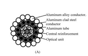
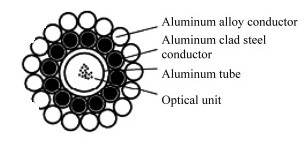
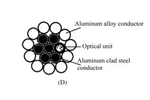
1 OPGW structure and classification
2 OPGW technical standards
International standards:
IEEE 1138-2009 Construction standards for composite optical fiber overhead ground wires for electric power lines
Optical fibre cables - Part 4-1: Combination specification - Aerial optical fibre cables for transmission lines.
Chinese national standard
GB / T 7424.4-2003: cable - Part 4: specification OPGW
Chinese industry standards:
Power industry standard DL/T 832-2016 fiber composite overhead ground wire
Mechanical industry standard JB/T 8999-2014 optical fiber composite overhead ground wire
3 OPGW electrical characteristics design
3.4 Selection and configuration of OPGW and shunt ground
Both the OPGW and the shunting ground wire shall meet the requirements of the design specifications of GB 50061-2010, GB 50545-2010, GB 50665-2011 and GB 50790-2013 for the mechanical and electrical use conditions of the ground wire, while having sufficient mechanical strength. It also has sufficient current carrying capacity to meet thermal stability requirements. The shunt ground should be able to effectively share the short-circuit current flowing through the ground. The model of the OPGW and the split ground wire and its segmented distribution scheme should be combined with the thermal stability check of the OPGW and determined by technical and economic comparison.
When selecting the PGW and the shunting ground structure, it is best to match the tension and the design sag characteristics as much as possible .
4 Mechanical properties of the OPGW
4.1 Design safety factor of OPGW
The design safety factor of the OPGW should not be less than 2.5 and should be greater than the design safety factor of the wire.
The maximum tension of the OPGW at the lowest point of the sag shall be calculated as follows:
T max ≤ T P / T C
In the formula:
T max — the maximum tension of the OPGW at the lowest point of the sag, N;
T P — rated breaking force of OPGW, N;
K C — The design safety factor of the OPGW.
The design safety factor of the suspension point should not be less than 2.25.The OPGW, which is mounted on the pulley, should also calculate the additional tension caused by the local bending of the suspension point. Under the meteorological conditions of rare wind speed or rare ice coating , the maximum tension of the OPGW at the suspension point should not exceed 66% of the rated breaking force.On the same line, when the calculation condition is +15 °C and there is no wind, the OPGW matches the design sag characteristics of the shunt ground, which should be consistent.
4.2 OPGW anti-vibration measures
The average operating tension of the OPGW should not be greater than 20% of the rated breaking force, and the corresponding anti-vibration measures should be taken according to the upper limit of the average operating tension.
The OPGW's annual average operating tension limit and corresponding anti-vibration measures shall be provided and accounted for by the suppliers of OPGW and supporting fittings. Anti-vibration measures for optical cables include shock-proof hammers and spiral dampers (anti-vibration whip).
a) Anti-vibration hammer: Anti-vibration hammer is a kind of adjusting frequency damper. It has very effective anti-vibration effect for large-diameter wires. The basic principle is to absorb energy dynamically. In general, the frequency damper has a specific frequency characteristic range. Commonly used in light ice areas, installation must be equipped with protective lines.
Number of anti-vibration hammer installations:
The installation distance of the anti-vibration hammer can be calculated as follows:
S1=0.4 × D ×( T/M ) 1/2 ( mm );
S2=0.7S1;
S3=S4=S5=...=0.6S1
among them:
D―——outer cable diameter (mm);
T―--annual average running tension (N);
M―——the unit weight of the optical cable (g/mm);
Precautions:
(1) According to the calculation, if the anti-vibration hammer calculation installation position falls on the inner skein, it is not necessary to install the guard line, and it can be directly installed.
(2) If the anti-vibration hammer calculation installation position falls on the OPGW cable, it is necessary to install the guard line, and note that the end of the guard line is at least 50-80 mm from the end of the inner skein.
(3) If the anti-vibration hammer calculation installation position falls on the outer skein, it is directly installed on the inner skein, and the center of the anti-vibration hammer is 50-80 mm from the end of the outer skein.
b) Helical damper (anti-vibration whip): anti-vibration whip (spiral anti-vibrator) is a commonly used shock damper, anti-vibration whip for small cable diameter transmission line and fiber line high frequency vibration reduction The vibration is very effective. The anti-vibration whip dissipates the vibration energy through the impact with the cable, thereby achieving the effect of weakening the line vibration. This type of damper is very effective for anti-vibration of small diameter wires, and its damping effect depends on the relationship between the quality and frequency of the anti-vibration whip and the wire. The heavy ice area cable line is characterized by large ice wind load and high material consumption. An effective anti-vibration measure for heavy ice areas is the use of a spiral vibration isolator.
(1) Anti-vibration measures in heavy ice areas
Since the anti-vibration hammer has anti-vibration failure in the case where the ice layer is thick, in addition, since the ice-skiping phenomenon is often accompanied by uneven de-icing, a spiral damper is used. It can play a good protective role for the dancing and jumping of the line.
(2) Anti-vibration scheme when using anti-vibration whip
Anti-vibration whip (spiral anti-vibrator) is currently the most commonly used impact damper, made of high-strength engineering plastic with impact resistance and anti-aging. The spiral vibration isolator consists of a clamping section and a vibration damping section. The clamping section grips the optical cable and dissipates the vibration energy through the impact of the vibration reduction section and the optical cable, thereby achieving the effect of weakening the line breeze vibration.
(3) Determination of the number of spiral dampers
Determine according to the line spacing:
When 0m < span ≤ 250m, install 6 (that is, install 3 on each side of the fitting)
When 250m
When 500m
When 750m
(4) Installation method
The installer sees the following figure:
The spiral damper is installed in the same position on the tension clamp or the suspension clamp. Generally, the first anti-vibration whip is installed at 150mm from the end of the inner skein, and the second is installed at 150mm from the end of the first anti-vibration whip. Where. This method is installed in series; it can also be installed in parallel or two stacked together, and the two installation methods have the same effect.
4.3 OPGW plastic elongation treatment
The plastic elongation of the OPGW after erection is determined according to the data provided by the manufacturer or by experiment. The influence of plastic elongation on the sag should be compensated by the cooling method. If there is no data, refer to the line GB.50545-2010. regulations, the author generally lower 15 ℃ more .
4.4 Other mechanical properties of OPGW
The calculation of OPGW mechanics is consistent with the calculation of the grounding line of overhead transmission lines. The parameters are not detailed here. If there is any problem, please leave a message to Xiaobian or join the 72468968QQ group for communication.
5 OPGW's distribution (length) calculation
The OPGW's distribution is a key part of the design process and determines the length of each OPGW. The arrangement of the distribution plate is directly related to the arrangement of the fiber optic connector. It also determines the installation interval of the OPGW and, if necessary, the direction of deployment.
5.1 OPGW distribution principle
The distribution plate shall obey the tensile section of the line. To reduce the fiber joint, two adjacent smaller tensile sections may be combined. Joints should be avoided in unfavorable terrain such as paddy fields, swamps, ponds, hilltops, and deep valleys, based on route data or site surveys. Joints should be arranged as far as possible in a location with convenient transportation and easy access to utilities. When there are two or more 90° rotation angles or more than four 45° rotation angles in the line, the discs should be divided as much as possible, and the joints should be arranged on these corner towers.
5.2 OPGW disk length
The distribution plate shall obey the tensile section of the line. To reduce the fiber joint, two adjacent smaller tensile sections may be combined. Joints should be avoided in unfavorable terrain such as paddy fields, swamps, ponds, hilltops, and deep valleys, based on route data or site surveys. Joints should be arranged as far as possible in a location with convenient transportation and easy access to utilities. When there are two or more 90° rotation angles or more than four 45° rotation angles in the line, the discs should be divided as much as possible, and the joints should be arranged on these corner towers.
In the plain area, a single plate of 3 to 5 km is a better choice. For example, in a mountainous area with complex terrain, it should be controlled as much as possible at a length of 3 km, so that a construction team can be discharged in one day. The length of the OPGW single disc also depends on the diameter of the monofilament of the stranded single wire, since the length of the single wire that can be accommodated on the work plate on the stranding machine is limited. When the long-length tensile section or the maximum single-disc length cannot meet the requirements of the tensile-resistant section, one treatment method is to reduce the diameter of the monofilament under the premise of maintaining the original aluminum-steel ratio, diameter and cross-section (to ensure The lightning protection performance, the diameter reduction is limited) is changed to multi-layer armor.
5.3 OPGW distribution length calculation
According to the relevant manufacturer's experience and the actual inspection of the relevant project, the length of the distribution plate can be calculated according to the formula:
D L =A×L+2(H+h)+2B
In the formula:
D L -- distribution length (m);
L -- line length (m);
A - length reserved coefficient: plain: 1.02 ~ 1.03; hills: 1.03 ~ 1.04; mountain area: 1.04 ~ 1.05;
H -- the height of the construction pulley from the input end of the cable (m) ;
h -- the height of the construction pulley off the ground at the output end of the cable (m) ;
B -- traction reserved length, usually 6 ~ 10m.
Due to the different geographical conditions of the area in which the cable is erected, the length of manufacture shall be determined on a case-by-case basis. The length of each OPGW is subject to manufacturing, transportation, construction and the limit of the site along the line, generally within 5km.
5.4 Reserved length of OPGW cable
In the maintenance work of the optical cable, the optical cable needs to be extended when the reconnecting box is partially moved. Therefore, reservations should be made in appropriate places during construction. This reserved length should be considered in the design length of the cable.
In the cable engineering, two reservation modes are usually adopted, one is the ordinary reservation mode (above figure a), which is used for telescopic bending on the pole . In areas with relatively wide terrain, this method is adopted, and the length is reserved. Within 5m; the other is the disc mode, which can be used when the terrain is limited or the reserved length is greater than 5m. The radius R of the curvature of the disk 6 is not to be less than the allowable radius of the cable, and the minimum bending radius of the cable is not to be less than 20 times the diameter of the light. Generally, the length of the cable for overhead erection and pipeline laying is 6~12m.
6 OPGW cable fittings
6.1 Configuration of OPGW fittings
The OPGW must use a dedicated pre-twisted fitting. The rated breaking strength and grip strength of the tensile-resistant fittings are both greater than 95% RTS. Under this tension, the fittings and OPGW are not allowed to have relative slip. The inner diameter of the pre-twisted wire of the sheet metal is directly related to the outer diameter of the cable. The outer diameter tolerance of the cable should be emphasized. The inner diameter of the pre-twisted wire of the fitting should be configured as far as possible according to the negative tolerance of the outer diameter of the OPGW. The holding force of the overhang (excluding the overhanging tensile) to the cable (horizontal sliding load) is generally 10 to 20% RTS.
In fitting configuration and selection, the tower selection of a set of terminal / base Clamp, strain tower use two sets / groups Strain line clip, straight tower selection of a set / group catenary clamp.
6.2 Design safety factor of fittings
The safety factor of the fittings shall comply with the requirements of the corresponding design rules for the transmission line. For general lines, the safety factor of the strength of the fittings should not be less than the following values (GB 50545-2010 6.03):
Maximum load condition 2.5
Disconnection, disconnection, check calculation 1.5
For large span lines, the safety factor of the strength of the fittings should not be less than the following values (DL/T 5485-2013 8.0.2):
Operation status 3.0
Wire break condition 2.0
Checking the situation 1.5
6.3 OPGW hanging metal string
The OPGW overhanging metal string is used to hang the OPGW on the linear tower. The pre-twisted type suspension clamps should be used. The pre-twisted suspension types are divided into single suspension clamps and double suspension clamps . The overhanging string must meet the load requirements and the short circuit current requirements of the line design .
Single suspension clamp
The single suspension clamp technology is characterized by a double-layer structure that provides greater protection for long-term unbalanced load-running cables, better dynamic stress tolerance, and improved grip. Due to the large contact area of the suspension clamp , the stress distribution is uniform, and there is no stress concentration point, which enhances the rigidity of the cable installation point and has a good protection effect on the optical cable. The materials selected have strong corrosion resistance, oxidation resistance and aging resistance, which greatly extend the service life. The structure is simple, the installation is very convenient, no special tools are needed, and maintenance is free.
Double suspension clampDouble suspension clamp mainly for large span rivers, high drop of valleys and other special places, the line of OPGW and ADSS turn angle in the tower of 25 ° ~ 60 °.
6.4 OPGW resistant sheet metal string
The OPGW sheet is used to withstand the tension of the OPGW. The OPGW is connected to the tension-resistant tower, and a pre-twisted type tension clamp is generally used. The tensile string must meet the load requirements and the short circuit current requirements of the line design .
The OPGW sheet metal fitting adopts a gold steel sand structure between the inner and outer stranded wires to increase the friction force, has a good protection effect and damping effect on the optical cable, and reduces the damage to the optical cable due to the dancing. Due to the large contact area, the stress distribution is uniform, and there is no stress concentration point, which has a good protection effect on the optical cable. The materials selected are highly resistant to corrosion, oxidation and aging. The structure is simple, the installation is very convenient, no special tools are needed, and maintenance is free.
6.5 OPGW anti-vibration hammer ( whip )
The OPGW anti-vibration hammer is used to control the breeze vibration of the OPGW caused by the wind. The anti-vibration hammer itself shall not cause stress concentration that causes damage to the OPGW, and the guard line shall be used at the installation position on the OPGW.
The anti-vibration measures in the heavy ice area adopt a spiral damper (anti-vibration whip). Spiral damper, commonly known as shockproof whip in engineering. It is a line protection device, which is used to eliminate or reduce the vibration generated by the laminar wind during operation of the optical cable to prevent damage to the metal fittings and the optical cable. The spiral damper is generally made of a high-strength PVC material in a spiral shape. A section with a small aperture is called a tightening section, and a section with a large aperture is called a damping section.
The factors that cause the cable vibration are: the length of the gear, the size of the tension, the wind speed, the wind direction, the topography and the structural size of the cable.
6.6 OPGW grounding down conductor
The OPGW should be reliably grounded, and another ground wire with shunting requirements should be reliably grounded.
Both the OPGW suspension string and the tensile string need to have a grounding lead, and the grounding lead should have a good mechanical and electrical connection with the OPGW and the tower.
When the OPGW is connected to the substation structure, the grounding line is reliably connected between the OPGW and the grounding grid connection point at the top of the substation structure. The cross-sectional area of the grounding line is the same as the OPGW cross-sectional area. In addition, between the OPGW connection box and the grounding point at the top of the frame, the OPGW and the substation frame transverse metal platform member grounding grid connection point or the substation ground grounding grid connection point are reliably connected by the grounding wire to ensure the OPGW and The substation grounding grid has a reliable second grounding point, and the grounding wire section is the same as the OPGW section.
6.7 OPGW connector box and down conductor
The OPGW splice box should be easy to install and maintain on the transmission line tower and easy to weld.
The joint box in the line should be installed on the designated tower and installed at a position 7m above the ground to prevent the destruction of mammals or artificial birds. The joint box on the side of the substation frame should be installed on the frame pillar. The installation position should be suitable for the operation personnel. The distance between the equipment and the live equipment in the station should meet the requirements of relevant regulations.
The down-conductor clip of the tower OPGW fiber should be installed on the tower leg without the nail; the fiber on both sides of the tension tower is led to the junction box through the double-slot down-clamp; the installation distance of the lower-clamp is : for the cross-arm part is about 1 meter, for the tower body part is about 1.5 meters; the front and rear side of the fiber-optic down-conductor line along the ground line cross-bearing slope main material into the inside of the tower body, leading to the 7 ~ 9 m from the ground After the surface, the remaining cable is placed in the remaining cable frame, and the bending radius of the remaining cable is more than 2 times the allowable bending radius; the optical fiber down-conductor has no hard bend and chamfer, and the down-conductor, the remaining cable frame and the junction box are firmly installed. The allowable bending radius of the OPGW down conductor at the bend should not be less than the value provided by the manufacturer.
The lead hoop of the OPGW fiber of the frame shall be installed on the frame; the cable shall be led to the remaining cable rack at 2.5 m from the ground to be welded by the lower clamp; the installation distance of the down clamp shall be 1.5 m, and the turn may be appropriate. Adjust the installation distance; note that the lower clamp should be installed firmly to ensure that the OPGW does not touch the steel;
6.8 OPGW residual cable rack
The OPGW residual cable frame is required to be easily installed and maintained on the transmission line tower. The minimum coil diameter of the remaining cable frame should not be less than the value provided by the OPGW manufacturer.
6.9 OPGW Optical Cable Distribution Frame (ODF)
The optical cable distribution frame is used for connecting and distributing the optical fiber cable and the FC/PC single-core optical fiber after the optical cable enters, and the optical path is wired and dispatched by the adapter. The technical requirements shall comply with the relevant provisions of YD/T 778-2011 "Fiber Distribution Frame".
When the cable is introduced into the rack, the bending radius should be no less than 15 times the diameter of the cable. When the cable fiber passes through the hole of the metal plate and turns along the sharp edge of the structural member, the protective cover and the gasket should be installed. When the fiber and pigtail are bent, the bending radius should be no less than 37.5mm.
7 frame to ODF frame guide cable selection design
7.1 Selection and structure of guiding cable
The ODF frame optical cable of the substation (station) to the communication equipment room should be made of non-metal ( high-voltage occasion ), good flame retardancy (substation fire protection requirements), layer- wound optical cable, and generally GYFTZY non-metal flame-retardant optical cable, as shown below.
The figures in the figure indicate:
1 Cable medium center reinforcement: Insulation rod with high tensile strength made of glass fiber reinforced plastic ( FRP ) , the tensile Young's modulus is not less than 50Gpa, and the bending Young's modulus is not less than 45Gpa. The rate is not less than 2% , and no joint is allowed within the manufacturing length of the cable.
2 fiber .
3 loose tube: The loose tube buffer tube made of high elastic thermoplastic material contains multiple optical fibers, and the tube is filled with water blocking compound, which has high waterproof and moisture resistance.
4 Filler: Made of highly elastic thermoplastic material, the color should be distinguished from the loose tube and can replace the loose tube in the core. The loose tube and the filler are stranded in a single layer around the central reinforcement.
5 cable core water blocking: the expansion material is used to prevent the longitudinal water intrusion of the cable core.
6 wrapped core: The stranded cable core is wrapped with moisture-proof belt to further strengthen the moisture-proof performance of the cable.
7 inner sheath: extruded with polyethylene, tightly wrapped fiber optic cable
⑧ cable strengthener: torsional torque balanced cable strengthener, high modulus aramid negative thermal expansion about the twisted wire spiral from the inner sheath to be opposite to the stranding direction aramid adjacent, outermost layer should be a right Spin. The Young's modulus is not less than 90 Gpa, and each bundle of aramid does not allow joints within the manufacturing length of the cable.
9 outer sheath: flame retardant / etch resistant polyethylene material .
7.2 Guide cable laying
The non-metallic guide cable should be placed in the semi-rigid plastic sleeve (PE or PVC material), and laid on the cable trench cable bracket in the station. In order to avoid misalignment, it should be fixed once every 2m, and ensure that the static bending radius of the cable is not less than The cable has 20 times the cable diameter, and the dynamic bending radius during construction is not less than 20 times the cable diameter. If a single-layer armored structure of the guiding cable is required, the design must consider good grounding at both ends, and if necessary, ground or multi-point grounding, and ensure that current is not introduced into the communication equipment.
In addition to the regulations mentioned in the reference text, this paper also refers to the " Design Depth and Technical Regulations of Optical Fiber Composite Overhead Ground Wire " of Guangdong Power Grid and the " Design of Optical Fiber Communication Lines for Power Systems" compiled by Yunnan Electric Power Design Institute.
Product Categories
Contact Us
|
Contact: Ms. Lisa Xiang (Director) Email:lisa.haichung@hotmail.com
Whatsapp:+8613968382831 Add:Xiangshan Ningbo, Zhejiang China.
|
|---|
|
|
|