





Overhead transmission line tension line construction
Overhead Transmission Line Tension Line Construction
Transmission and distribution lines | Updated: 2017-07-10
1. Overview
Tension wire construction stretches conductors under controlled tension to maintain an overhead state throughout the pay-off process—preventing ground contact and minimizing friction.
Key features:
- The construction section differs from non-tension methods: starting and ending towers should be as straight as possible.
- The section may form part of a tensile or spanning segment.
Advantages: High conductor quality, high mechanization level, fast and efficient operation.
Per Code for Construction and Acceptance of 110–750kV Overhead Transmission Lines (GB 50233–2014), Article 8.2.1, tension laying is mandatory in the following cases:
- Line projects with voltage level ≥ 220 kV;
- 110 kV line projects;
- Good-conductivity overhead ground wires.
Additional requirements are specified in DL/T 5343, Construction Process Guide for Tension Laying of 750 kV Overhead Power Transmission Lines.
2. Tension Wire Construction Preparation
(1) Pre-construction Preparation
Includes: construction survey report, technical documentation, technical briefing, tooling & material preparation, engineering tests, trial runs, and site readiness.
(2) Construction Section Division
Per GB 50233–2014, Article 8.2.5:
- Maximum length of a tension section: ≤ 20 pulleys.
- If exceeded, protective measures must be implemented.
Article 8.2.6 further requires shortening the section when crossing critical infrastructure. Typical length: 3–8 km.
However, complex terrain or unavoidable major crossings may necessitate longer sections (e.g., 14 km in the Second (Beach)–Zigong 500 kV line). Also, accessories must be installed within 72 hours after ground wire tensioning—supporting moderate section lengths.
(3) Basic Elements of Traction & Tension Fields
Per GB 50233–2014, Article 8.2.8:
- Traction field: preferably aligned with the line; steering via blocks permitted if terrain-limited.
- Tension field: should not be steered; if unavoidable, steering block position and angle must comply with tension equipment specifications.
Unsuitable locations for traction/tension fields:
- Sections where joints in guide/ground wires are prohibited;
- Immediately before/after tension towers or straight-angle towers (anchoring constraints);
- Important crossing zones;
- Low-lying, flood-prone areas;
- Locations before/after wire lifting points.
Space requirements:
| Field Type | Minimum Area |
|---|---|
| Tension field | ≈ 75 × 25 m |
| Traction field | ≈ 35 × 25 m |
To minimize transitions, local adjustment using tension functions is recommended.
(4) Site Layout
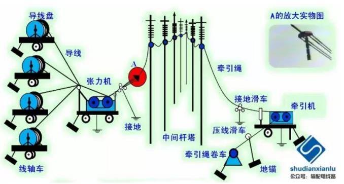
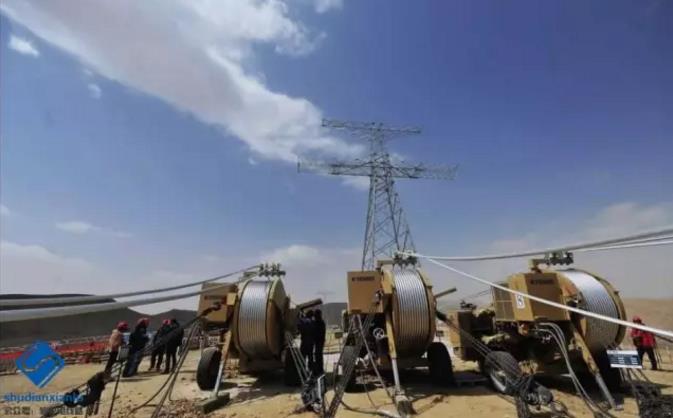
See Figure 2-1 below:
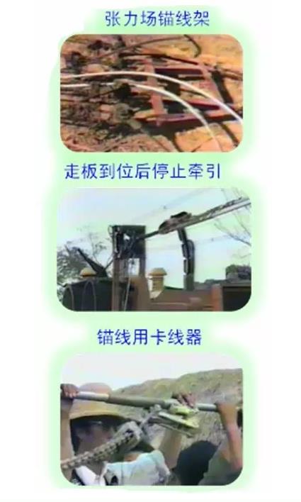
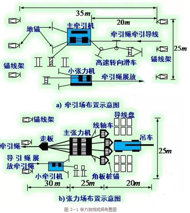
Figure 2-1: Tension line layout
3. Tension Release
(1) Tension Construction & Grounding
Guide ropes (manually or mechanically deployed) pull ground wires. Alternatively, manual laying may be used, followed by tightening and hanging.
(2) Tension Spreader Wire Process
Steps include:
- Take-up preparation;
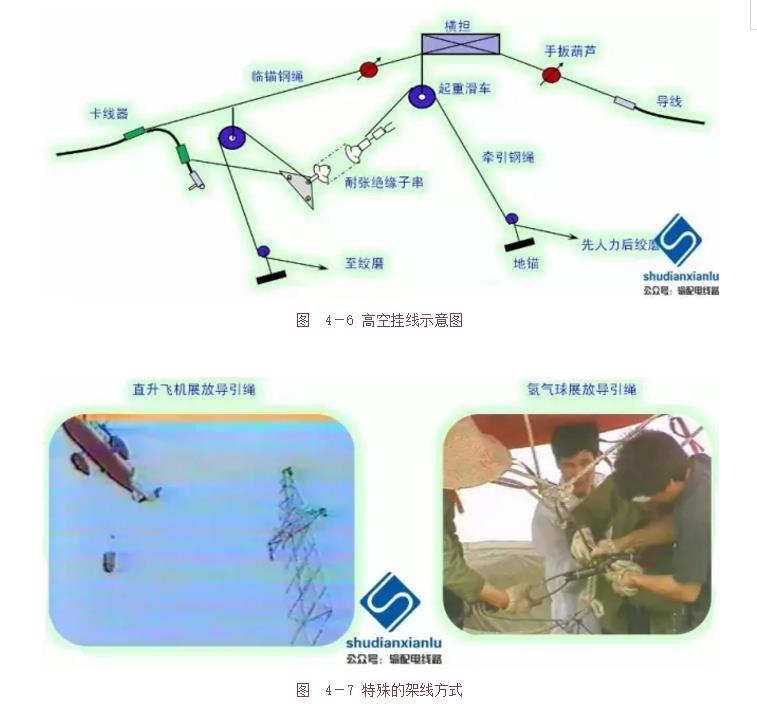
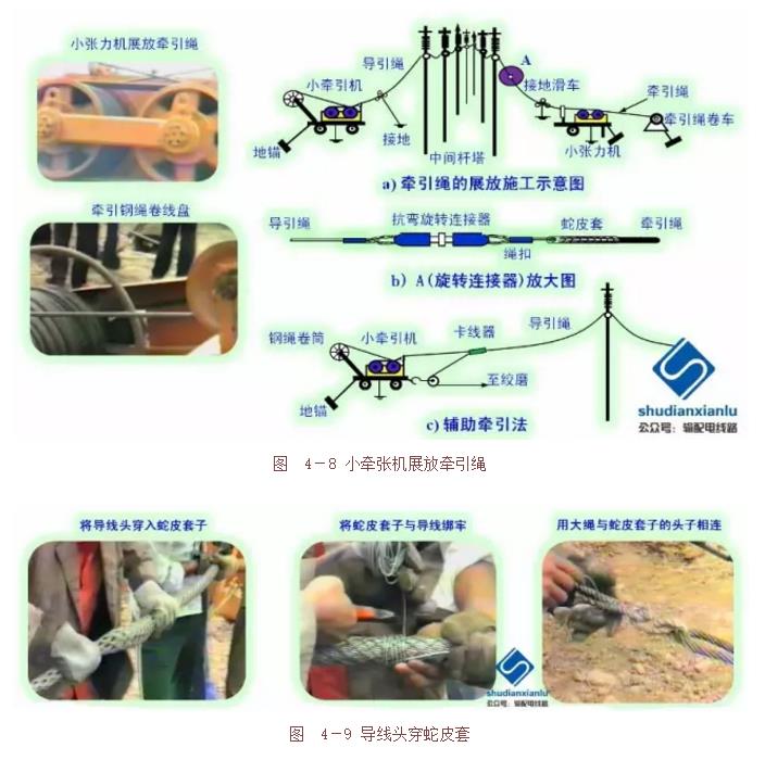
- Guide rope deployment (Φ8–Φ10 mm special traction steel rope; deployable via manpower, helicopter, or airship);
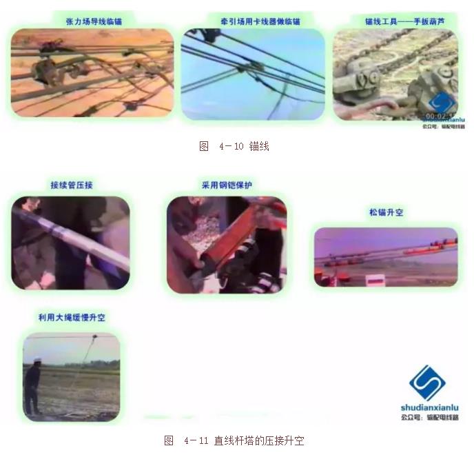
- Anchoring;
- Tension display rope (Φ19–Φ22 mm special traction steel rope);
- Tension display wire (with real-time monitoring);
- Lifting towers: use pressure-line pulleys (see Figure 3-1);
- New wire reels: apply snake-leather covers during towing (see Figure 3-2);
- Final anchoring.
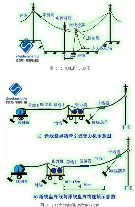
Figure 3-1: Pressure-line pulley schematic
Figure 3-2: New spool replacement process for tension release
(3) Key Precautions
- Unified command and coordinated operation;
- Stable, accurate movement; timely adjustments;
- Enhanced monitoring—especially of pressure-line pulleys;
- Prevent whiplash: anchor only after full release; arrange four sub-wires at unequal heights;
- Immediate work stoppage upon abnormal conditions.
(4) Take-up Tension Calculation
Horizontal tension at control span:
(p = overhead line unit load; k = control span factor)
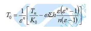
Tension machine outlet tension:
In the formula:
- Ε = pulley friction coefficient (1.012–1.015);
- Ω = self-weight of wire/traction rope (kN/m);
- ∑h = cumulative elevation difference from control span to tension machine exit (m);
- n = number of pulleys between control gear and tension machine exit (including exit roller);
- K₀ = 1.1.
(5) Traction Force Calculation
Final traction force:
(m = number of empty lines in traction frame; other symbols as defined above)
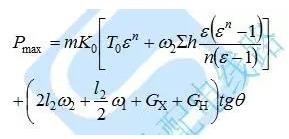
Maximum traction force:
In the formula:
- L₂ = vertical distance to first tower adjacent to tractor side (m);
- GX = suspended insulator weight (kg);
- GH = take-up block weight (kg);
- Θ = suspension insulator string inclination angle (typically 20°);
- Ω₁ = traction rope unit weight (kN/m);
- Ω₂ = towing rope unit weight (kN/m).
(6) Damage Treatment Standards
| Damage Level | Criteria | Treatment |
|---|---|---|
| Minor | Scratch depth ≤ 1/4 strand diameter; cross-sectional damage ≤ 2% of conductive area | No repair needed; polish surface with fine sandpaper (#0 or finer) |
| Moderate | Strength loss ≤ 8.5% of designed breaking force; cross-sectional damage ≤ 12.5% of conductive area | Repair with pre-twisted wire or silicon carbide–coated pre-twisted wire per GB 50233–2014, Section 8.3.3 |
| Severe | Any of the following:• Strength loss > 8.5% of designed breaking force• Cross-sectional damage > 12.5% of conductive area• Damage exceeds pre-twisted wire repair limits• Broken steel core strands• Permanent deformation (e.g., gold hooks, lanterns, strand distortion) | Cut out damaged section; reconnect using compression splice or corundum pre-twisted wire |
4. Tension Line Tightening
(1) Free Tight Line
Similar to floor-laying tight line: one end anchored, the other tightened. Key distinction: ends are typically linear towers, with anchoring at the fixed end.
Since both tension and traction fields are located at linear towers—and the ground wire is isolated from adjacent sections—a straight-line crimping lift (“linear tower crimping lift”) is performed before tensioning. See Figure 4-1.
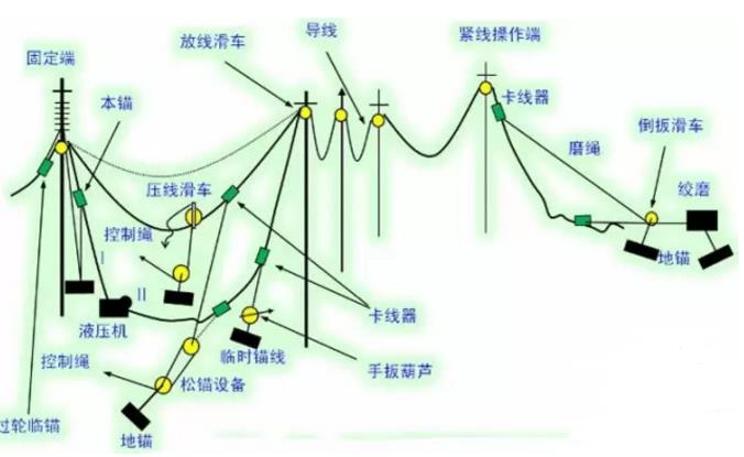
Figure 4-1: Schematic diagram of tension tight line construction
(2) Tight Line Construction Process
- Anchoring and reversal at operating end (fixed end of section);
- Connecting wire ends via linear crimping pipe, then lifting;
- Remaining line handling, sag observation, and adjustment (tight-to-loose → tight adjustment method);
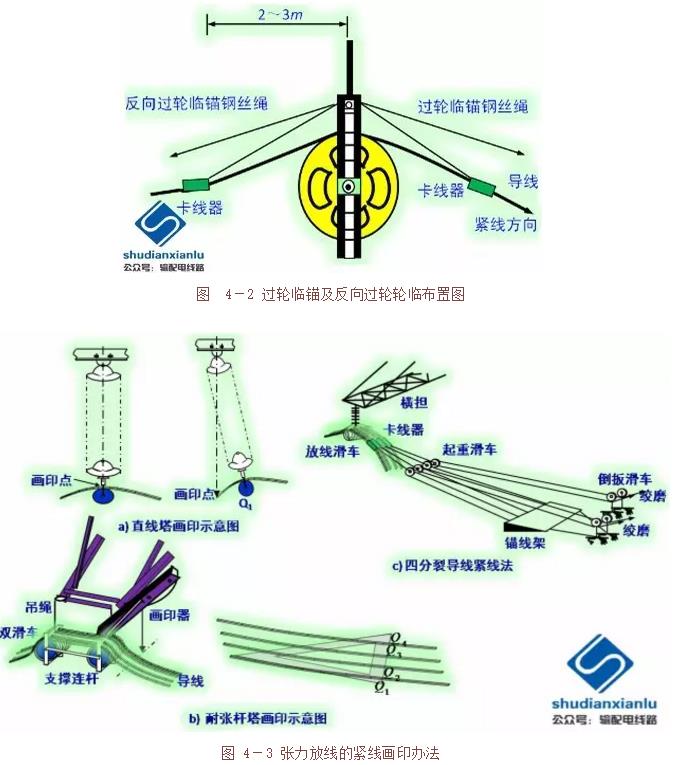
- Marking (same as floor-laying process);
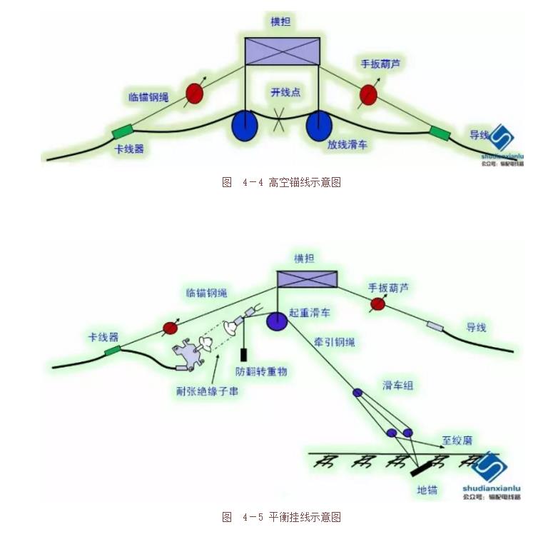
- Hanging line using balanced hanging method:
- • High-altitude anchoring (Figure 4-4)
- • Wire cutting, crimping of tension clamps
- • Balanced hanging (Figures 4-5 & 4-6)