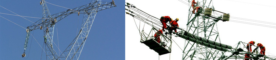
Overhead line sag observation and inspection operation
Overhead line sag observation and inspection operation
http://www.reach-power.com/Products/products_98.html?l=en-us
1.0 The effect of sag
In line design, by strictly calculating the determined sag value, sufficient safety distance can be ensured to the ground and the crossed objects, and the line stress can be ensured within the allowable range. During construction, according to the designed sag value, the observed sag can be calculated and strictly observed and checked, so as to ensure the construction quality and the safe operation of the line.
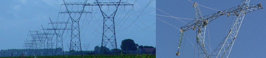
2.0 The concept of overhead line sag
2.1 The concept of sag
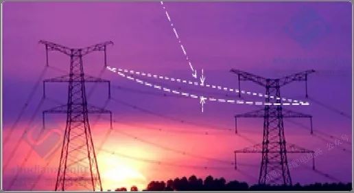
Simply put, the degree of relaxation is the degree of relaxation of the overhead line behind the overhead line. Considering the thermal expansion and contraction, the overhead line can not be a straight line, but a different size arc. This arc is the expression of sag, so sag (f) is also called sag.
2.2 Common sag types
Contour condition
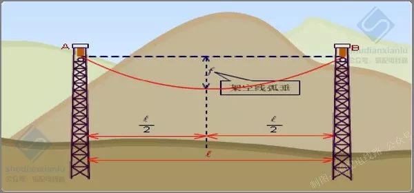
Hung on the overhead line A and B under the conditions of high F sag at exactly the span midpoint.
.............................................
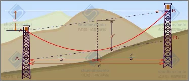
Elevated line unequal height
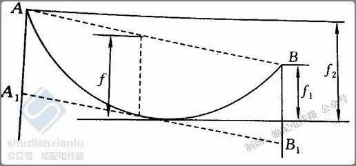
There are two sags in the case of unequal elevation of overhead lines.
.............................................
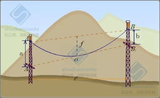
Generally speaking, sag refers to the vertical distance f between the tangent A1B1 of the overhead line sag made by parallel two suspension points A and B and the midpoint of the AB straight line, also known as the midpoint sag.
3.2 Operational Regulations for Sag Observation
1. The observed sag temperature is based on the average temperature of each observation stall and tightening tower.
2. The conductor thermometer is used to measure the temperature, and the conductor thermometer is suspended at the position equal to the average height of the conductor when the tower body is selected. The bar thermometer is placed in a longer wiring section to extract the steel core and suspended in the sun.
3. After hanging up the line, the sag of the observation gear must be retested once, and records should be made, and the sag observation record form should be filled in.
.............................................
2.4 Technical principle
Basic Principles for Choosing Observation Documents
The basic principle is: in the construction of tight line, it can sensitively respond to the stress and sag changes in the tension section, and it is representative; at the same time, it is necessary to focus on the observation of key lines. The selection of observation stalls is related to the number of stalls, the distance between stalls and the difference of suspension height.
1. Choose one close to the middle when the tightening section is in the 5th gear or below.
2. When the tightening segment is in gear 6-12, choose one gear near each end.
3. When the tightening segment is above 12 gears, choose one gear near the two ends and one gear in the middle.
4. Wire gears with larger gear spacing, smaller height difference between suspension points and close to representative gear spacing should be selected for observation gear. 5. The number of sag observation ports can be increased appropriately according to the site conditions, but not reduced.
6. The position of observation stalls should be evenly distributed, and the distance between adjacent observation stalls should not exceed 4 line stalls.
7. The observation file should be representative. For example, in the high and low places of continuous inclined gears, the front and back sides of higher suspension points, and the joint of adjacent tight lines, observation files should be set near the important crossed objects.
8. It is advisable to select tower numbers with large monitoring range for adjacent line files as observation points.
9. It is not advisable to select the line gear adjacent to the corner tower as the observation file.
To calculate the sag of the observation gear:
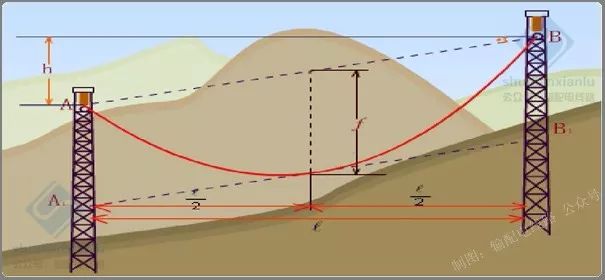
When the difference of suspension height h is less than 10% L (regarded as equal height)

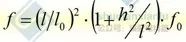
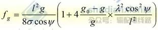
When the difference of suspension height h>10%l
Sag calculation of isolated gear
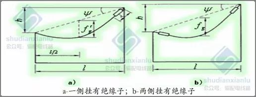
The sag observation
value of insulator strings hanging on the side of isolated gear during construction
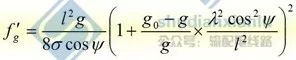
After completion, the central sag of insulator strings hanging on both sides of the isolated gear is as follows
03 Construction method of sag
3.1 Equal length method
Equal length method is also called parallelogram method.
Key points: a = b = f
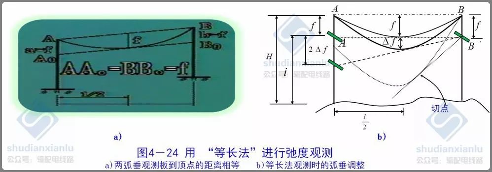
The accuracy of sag measurement by equal length method decreases with the increase of overhead suspension height difference. When the height difference is zero, the connection between the two observation panels is just tangent to the lowest sag point. With the increase of the height difference, the tangent point will gradually move away from the lowest sag point, and even the sag can not be observed by this method. As shown by the dotted line in the figure above, there is no intersection point on the A-pole tower after it is tangent to the catenary from the B-observation plate.
Conditions for the use of the equal-length method:
H < 0.2 L F < H - I
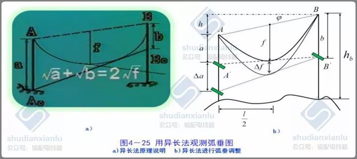
3.2 Different length method
To observe sag with different length method is to select an appropriate a value according to the sag calculation value f of the observation file, and then calculate B value.
When checking the sag, the actual sag F value of the checking gear is deduced from the A and b values on the towers on both sides of the checking gear.
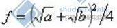
Note: The method of different lengths refers to a relaxation observation method that the position of the relaxation observation board arranged at both ends of the gear is not equal to that of the suspension point. Similarly, it also depends on the tangent of the lowest sag point of the guide line to the line of the observation board to determine whether the sag has met the requirements.
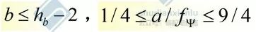
The observation method of heterodyne method is shown in Fig. 4-25. When a > 4f (b = 0), the heterodyne method is not applicable.
Determine the viewpoint:
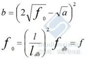
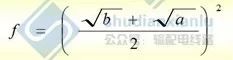
1. When the height difference of the suspension point h is less than 10% L, the observation end chooses a suitable value, and the vertical distance of the suspension point at the viewpoint end below the homologous overhead line is B. The calculation formula is as follows:
2. When the height difference of the suspension point h is more than 10% L, the observation end chooses a suitable value, and the vertical distance of the suspension point at the viewpoint end is b, which is lower than the suspension point of the overhead line on the same side.
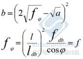
Formula:
Ldb, FDB - stands for pitch and sag;
_-elevation difference angle
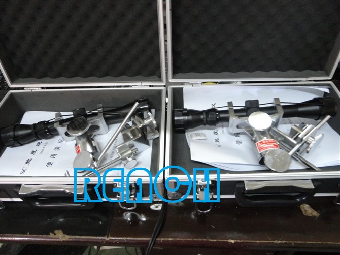
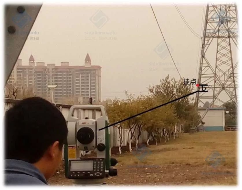
3.3 Angle method
Angle method is a method of measuring sag vertically and intuitively by theodolite.
Observing methods at any point of the gear end, the gear side, the inside and outside of the gear.
Which method to choose depends on the topographic conditions and the actual situation, and the end-to-end angle method is the most used. Compared with other methods, the angle method needs more measurements, has a larger amount of calculation, and has a greater possibility of causing errors, so it is generally less used.
In the observation of sag, theodolite is placed at the end of the observation file to observe the elevation of the lowest sag of the ground guide line. Make theodolite line of sight and wire phase When tightening the line, the theodolite line of sight and the wire are tangent, so that the sag is obtained. It is suitable for hills, mountains, gullies and so on. It is not suitable for terrain conditions of equal length method and different length method. According to the different positions of theodolite arrangement, it can be divided into: end-to-end angle method, inside-out angle method, side-to-side angle method, head-up method, etc.
Operating Conditions of Angle Method
The more commonly used end-to-end angle method
Theta-angle observation, (?) (positive value is elevation, negative value is pitch angle);
The vertical distance between the center of a telescope and the point near the suspension can be measured directly, M.
When the height difference between suspension points (near the suspension point (i.e., the observation end) is low, take "+" and vice versa, m;
F - Overhead line sag of observation gear, m;
L-Observing Gear Spacing, M.
It can be seen from the above that all the data needed can be obtained from the drawings, and the sag of the acting line can be observed after fixing the angle. Picture Angle Method to Check Sag
Angle method for sag detection
Fig. 1: Sag retest, b value can be measured according to the point of view intersection, then f value can be found through drawings, using formulas:
The inclination theta can also be determined, A and height difference h can be obtained,
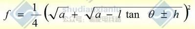
and formulas can be used to calculate the inclination theta of the steep steep steep steep steep steep steep steep steep steep steep steep steep steep steep steep stee
The existing sag of the conductor is calculated.
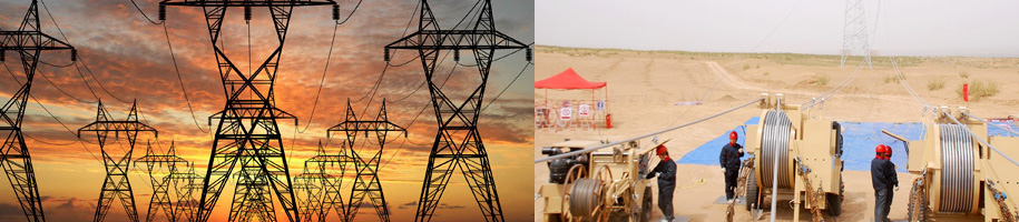
Sag observation and inspection are often used in the construction and operation of transmission lines. In order to ensure the safety of construction and operation, it is important to correctly observe the sag for long-term operation of ground conductors within the stress range allowed for long-term use. At the same time, the sag observation operation collects more data, requires higher accuracy, and requires a larger amount of calculation. It is a more rigorous operation. For the operator, it should be thoughtful, careful and careful, and the operation process is not affected by external factors.
Product Categories
Contact Us
|
Contact: Ms. Lisa Xiang (Director) Email:lisa.haichung@hotmail.com
Whatsapp:+8613968382831 Add:Xiangshan Ningbo, Zhejiang China.
|
|---|
|
|
|