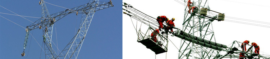
Overhead transmission line tension line construction
Overhead transmission line tension line construction
Transmission and distribution lines 2017-07-10
1 Overview
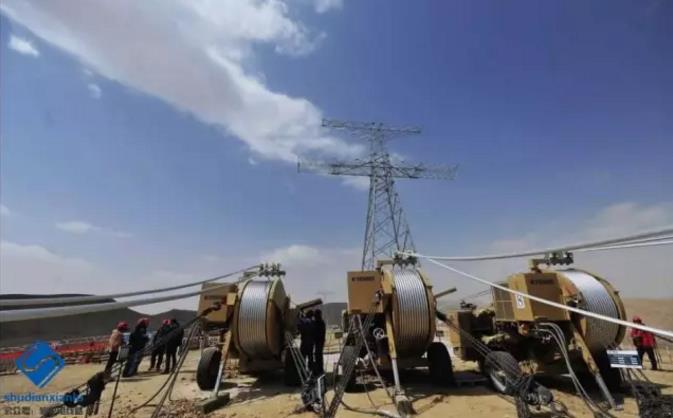
Tension wire is used to stretch the wire by tension.
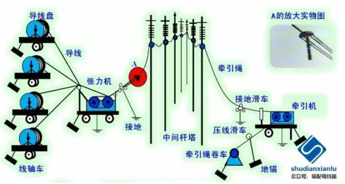
The wires are always in an overhead state during the entire pay-off process to avoid friction between the wires and the ground. The construction layout is shown in Figure 1-1. Features: The construction section of the tension wire is different from the non-tension wire. The starting and stopping tower should be as straight as possible, that is to say, the construction section may be part of the tensile section or the spanning section.
Figure 1-1 Schematic diagram of tension laying
Tension wire has many advantages: the quality of the wire is good; the degree of mechanization is high; the speed of the wire is fast and efficient. Therefore, China currently stipulates in Article 8.2.1 of the “Code for Construction and Acceptance of 110~750kV Overhead Transmission Lines” (GB 50233-2014): In addition to the following requirements, the tension discharge operation should comply with the current industry standard “750kV overhead”. Provisions for the construction process guide for the tension line of power transmission lines DL/T 5343:
1. Wire tensioning of line engineering with voltage level of 220V and above should be taken by tension.
2. The tension of the 110kV line project should be tensioned;
3, good conductor overhead ground wire should be tensioned.
2 tension wire construction preparation
(1) Preparation before construction
Including: construction survey report, technical data preparation, technical disclosure, preparation of tools and materials, engineering test and necessary trial exercise, site preparation.
(2) Division of construction section
Article 8.2.5 of the “Code for Construction and Acceptance of 110~750kV Overhead Transmission Lines” (GB 50233-2014) stipulates that the length of the tension line section should not exceed 20 pulleys. When it is difficult to meet the requirements, protective measures should be taken. Article 8.2.6 stipulates that in the tension laying line, when the important crossing is passed, the length of the tension paying section should be appropriately shortened. The mileage is generally 3 to 8 km. However, during construction, it is often encountered that the terrain is complex or important cross-over and cannot be set up, and the field needs to be extended. For example, in the construction of the second (Beach)-Self (Gong) 500kV line, there was a construction section of about 14km. In addition, the installation of the accessories should be completed within 72 hours after the ground wire is tight. This also shows that the construction section should not be too long.
(3) Basic elements of the stretch field
Article 8.2.8 of the “Code for Construction and Acceptance of 110~750kV Overhead Transmission Lines” (GB 50233-2014) stipulates that the traction field shall be arranged along the line. When limited by terrain, the traction field can be steered through the steering block. The tension field should not be steered. In special cases, when the steering must be arranged, the position and angle of the steering block should meet the requirements of the tension wire.
The places where the stretch field is not suitable are: the line file that does not allow the guide and the ground wire to have joints; the front and rear of the tension bar tower; the front and rear of the straight corner pole tower (inconvenient due to anchoring); the important cross-over crossing; the low-lying, easy-to-water accumulation. The pull and the field should be set before and after the wire is lifted up.
Due to the number of equipment and reels, the tension field requires about 75×25m of ground; the traction field needs about 35×25m; to reduce the number of tension field transitions, the tension function should be used for local adjustment.
(4) Site layout of the construction section
See Figure 2-1 below.
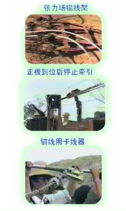
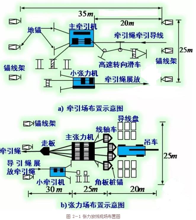
Figure 2-1 Tension line layout
3 tension release
(1) Tension construction and grounding construction
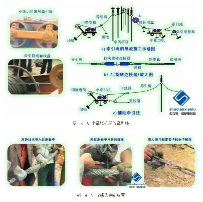
The man-made display guide rope is used to pull the ground wire with a small pull and a machine to guide the rope. It is also possible to use the manpower to lay the ground wire and complete the tightening and hanging operation.
(2) Tension spreader wire construction process
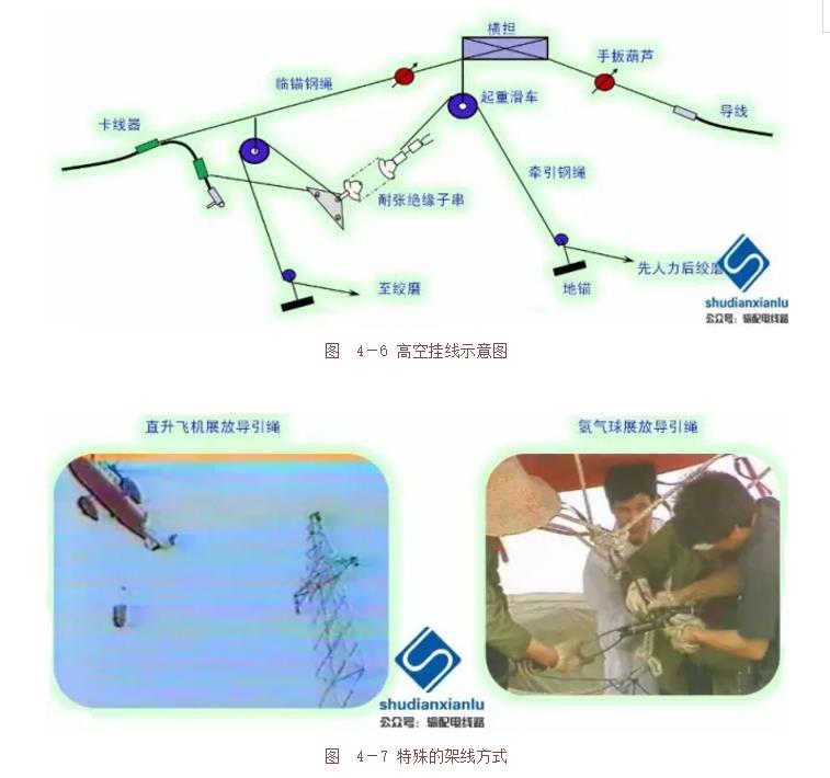
Take-up preparation, display guide rope (special traction steel rope of Φ8~Φ10mm) (can be used for manpower, helicopter, airship, etc.), anchor rope, tension display rope (Φ19~Φ22mm Special traction steel rope), tension display wire (to do the monitoring work; the lifting tower should use the pressure line pulley, as shown in Figure 3-1; the new wire disk application snake leather cover towing the big wheel as shown in Figure 3-2) , anchor line.
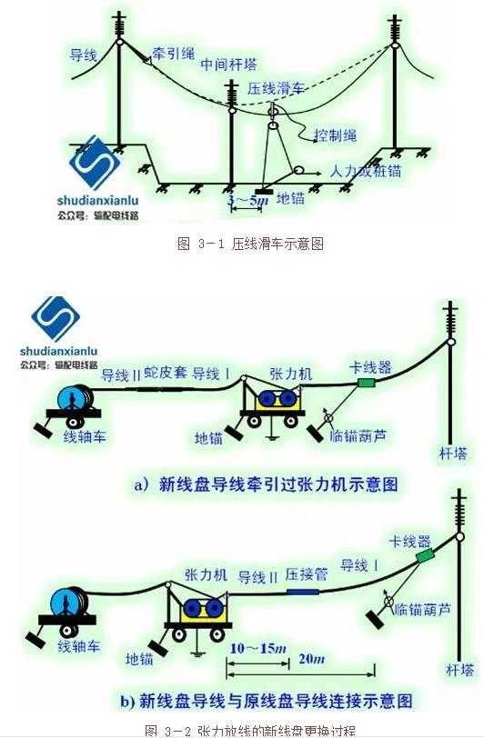
Figure 3-1 Schematic diagram of the press line block
Figure 3-2 New spool replacement process for tension release
(3) Precautions for tension line construction
Unified command; stable and accurate walking, timely adjustment; strengthen monitoring, especially the pressure line pulley; to prevent whiplash, the anchor should be carried out after the exhibition is released, and the four sub-wires should be arranged in unequal heights; The job should be stopped.
(4) Calculation of the take-up tension:
The horizontal tension of the control file:
(p overhead line unit load, k control template factor)
Tension machine outlet tension:
In the formula:
Ε-- release block friction coefficient, take 1.012 ~ 1.015;
Ω--the self-weight kN/m of the wire and the traction rope;
∑h--The cumulative height difference from the tension control file to the wire suspension point at the exit of the tension machine [the tension machine side is positive, vice versa] m;
n--Number of pulleys passing through the control gear to the exit of the tension machine at the exit of the rope or wire [including the tension roller exit roller];
K0--take 1.1.
(5) Calculation of traction:
The calculation formula of the final traction:
(m is the number of empty lines in the traction frame, the meaning of the rest of the letters is the same as the tension calculation)
The calculation formula of the maximum traction:
In the formula:
L2--the vertical distance of the first base tower adjacent to the tractor side of the construction section, m;
GX--the weight of the suspended insulator, kg;
GH--weight of the take-up block, kg;
Θ--the inclination angle of the suspension insulator string when the board is over the trolley, generally takes 20°;
Ω1-- traction wire rope unit weight, kN / m;
Ω2--towing wire rope unit weight, kN/m. )
(6) Damage treatment standard for tension wire
1) Minor damage to the outer wire strands is slightly scratched, the depth of the scratch does not exceed 1/4 of the diameter of the single strand, or the cross-sectional area damage does not exceed 2% of the cross-sectional area of the conductive part, may not be repaired, available below 0# The fine sandpaper is polished on the surface.
2) Moderate damage When the wire damage has exceeded the minor damage, but the strength loss of the same damage is not more than 8.5% of the designed breaking force or the damage sectional area does not exceed 12.5% of the cross-sectional area of the conductive part, it should be moderate. damage. Moderate damage should be repaired with pre-twisted wire or pre-twisted wire with silicon carbide. The repair should be in accordance with Section 8.3.3 of Section 4 of the “110-750kV Overhead Transmission Line Construction and Acceptance Code” (GB 50233-2014). Provisions.
3) Severe damage It should be determined as serious damage in one of the following cases. When serious damage is reached, the damaged part should be sawn off completely, and the connecting wire or pre-twisted wire with corundum should be used to reconnect the wire:
1) The strength loss exceeds 8.5% of the design calculation of the breaking force;
2) The cross-sectional area damage exceeds 12.5% of the cross-sectional area of the conductive portion;
3) The extent of damage exceeds the range of repairs allowed for a pre-twisted wire;
4) The steel core has broken strands;
5) Gold hooks, strands and lanterns have caused the steel core or inner strands to form irreparable permanent deformation.
4 tension line
(1) Free tight line
It has the same points as the mopping floor display: one end is anchored and the other end is tightly operated; different points: the ends of the tension tight line construction section are mostly linear pole towers, and the anchoring line is anchored at the fixed end.
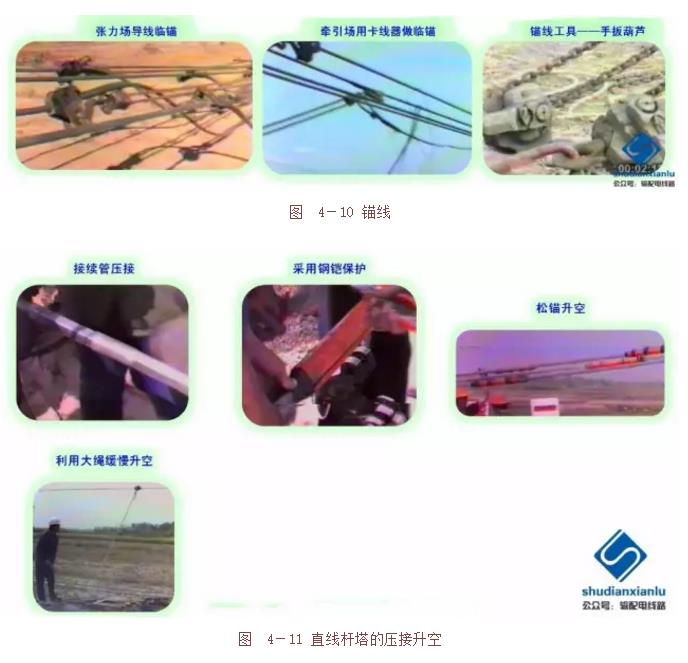
Since the tension field and the traction field are at the linear tower, and the grounding line and the adjacent construction section are separated, they are not continuous. Therefore, before the tension is applied, the ground wire of the tension machine (or the tractor) should be connected in a straight line before lifting. It is called a linear tower crimping lift. The basic procedure is shown in Figure 4-1.
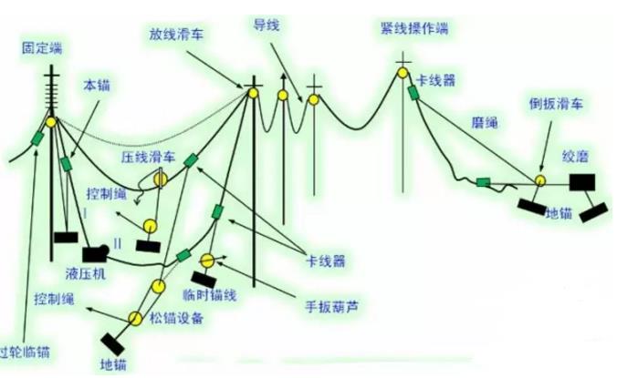
Figure 4-1 Schematic diagram of tension tight line construction
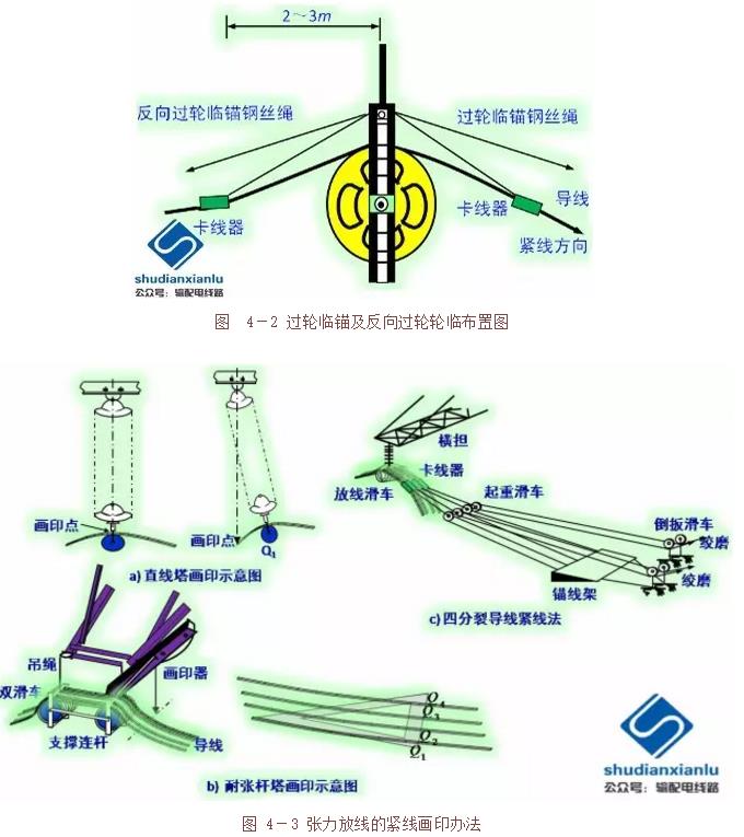
(2) tight line construction
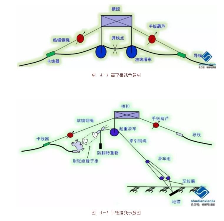
Tight line construction process: the wheel is anchored and reversed at the operating end of the tight line section (fixed end of the tight line construction section), as shown in Figure 4-2; the tight line section and the tight section The wire ends are connected by a linear crimping pipe and then lifted off; the remaining line, the observation sag and the adjustment (tight to loose ~ tight adjustment method), and the printing (Figure 4-3) (the same process as dragging the floor) ); hanging line (balanced hanging line process: high-altitude anchor (Figure 4-4), wire secant breaking and crimping tensile clamp, balanced hanging line (as shown in Figure 4-5 and Figure 4-6) )).
Product Categories
Contact Us
|
Contact: Ms. Lisa Xiang (Director) Email:lisa.haichung@hotmail.com
Whatsapp:+8613968382831 Add:Xiangshan Ningbo, Zhejiang China.
|
|---|
|
|
|