Home > News
News
Falling type gin pole erection method and stress requirements for 15m street lighting pole
Falling type herringbone pole method and stress requirements
table of Contents
Summary
Chapter 1 Construction Precautions - 1 -
1.1 Construction Preparation - 1 -
1.2 Site layout - 1 -
1.3 Pole standing up - 5 -
1.4 Selection of lifting points - 6 -
1.5 Overall standing - 7 -
1.6 Fastening, Transition - 8 -
Chapter II Force Calculation - 9 -
2.1 Live Mapping - 9 -
2.2 Ground rotation method - 10 -
2.3 Graphic method for the force of each device during the tower erection process - 12 -
2.4 Number Solution - 14 -
Chapter III Lifting the Cap to Remove the Cap - 16 -
3.1 The meaning of the pole off the cap - 16 -
3.2 Factors affecting the morning and evening of the poles - 16 -
3.3 The ideal uncap state of the pole - 17 -
3.4 Adjustment method of the capping angle of the pole - 17 -
3.5 Special terrain poles - 18 -
References - 18 -
Summary
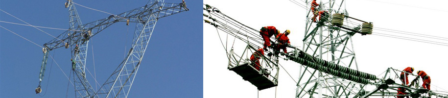
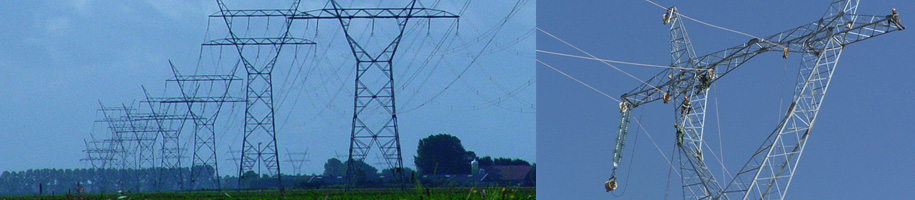
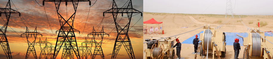
The falling type herringbone pole is easy to install and the equipment is stable and reliable. Because it is the difficulty of reducing the height work in the whole assembly, the advantage is that the poles with more than 2 times the pole height can be lifted by the less high poles, and the main operation post is safer to lift than the distance of the reverse pole. A main construction method for tower erection in electric construction. The construction process is shown in the following figure:
The overall assembly tower of the falling pole is to increase the traction fulcrum by the height of the pole. The pole rotates around the fulcrum of the ground with the erection of the tower until the head of the tower rises to the pole failure. Take off the cap, and then directly straighten the tower by the traction rope to complete the task of assembling the tower. In this paper, the tools and precautions for the need of the inverted type of human-shaped poles in the vertical tower are studied, and the force of the herringbone is studied to improve the effectiveness and safety of the tower.
Chapter 1 Construction Precautions
1.1 Construction preparation
1. It is necessary to prepare the technology before assembly: the inverted pole pole tower is a relatively complicated construction process, which is subject to different terrain, terrain, non-tower type, different grouping methods, so in each Before the foundation tower is set up, a detailed investigation of the construction site must be carried out, and targeted construction plans and safety measures should be formulated according to local conditions.
2. Personnel organization preparation: According to the proposed construction plan, according to the construction difficulty and the amount of engineering quantity, determine the number of technicians and general workers required at the site, and clarify the on-site construction person in charge, technical leader, safety officer and pole, traction, Responsible persons in various parts such as braking, temporary pulling and observation points shall be uniformly commanded by the person in charge of construction and a deputy commander shall be established.
3. Preparation of construction tools and equipment: Careful analysis of the location and stress of each construction stage, and the rational selection of construction tools and equipment is crucial in the process of setting up the pole tower. The selected poles, capping rings, traction steel ropes, hanging point ropes, brake steel ropes and pulleys, ground anchors and traction equipment of various specifications shall be carefully checked. Preparation should be sufficient and leave some room for it.
1.2 Site layout
Site layout is a key process for the overall assembly of the tower. The quality of the site layout work, the speed is directly related to the ability to complete the tower assembly task with high quality, safety and efficiency. The basic task of site layout is to do all the work before the tower is completed in accordance with the requirements of the construction plan and measures. The basic contents are as follows:
1. Arrange and fix the steel rope system, traction system and power system.
2, the position of the pole, installation (including the steering system of the air steering).
3. Arrange the brake steel rope system.
4. Prepare the temporary cable drawing system and the production of the long-term cable.
5. Arrange the ground anchors for excavation, traction, steering, braking or iron tower turn and temporary pull.
6. Do a good job in preparing materials and materials for the reinforcement of the tower body.
7, other.
The main contents of the site layout work are detailed below:
1.2.1 Fixed steel rope system
The fixed wire rope system is also called the lifting system. From the lifting of the tower to the fixed block of the head of the pole (the uncap system), all the lifting slings with the fixed point bundled steel rope are collectively called the fixed steel rope system. It is composed of lifting steel ropes, pulleys and lashing steel rope sleeves. Lifting and tying points are also called fixed points. When multi-point lifting is used, the arrangement numbers of the fixed points are usually arranged downward from the top of the tower.
(1) According to the conditions of the center of gravity of the tower and the height of the structure, a reasonable fixed point position should be selected after calculation, and the binding position should be measured on the tower to make a record.
(2) When the two points are fixed, the two ends of the fixed steel rope are directly wound around the fixed point of the tower for 1~3 times and then connected by a U-ring. When fixing the three points, the short steel rope sleeve should be fixed on the first and second fixed points, and the balance pulley should be added in the middle. Then, one end of the steel rope sleeve is fixed to the third point, and the other end is connected to the balance pulley through the pulley. . It can also be reversed; long steel rope sets are fixed at 1, and short rope sets are fixed at points 2 and 3, depending on the situation. The fixed fixed point of four points is nothing more than adding a balance block and a short steel rope. There are four ways to arrange it, so there is no need to introduce it here.
(3) The binding method of the fixed rope sleeve on the pole tower is: when the two points are fixed, the winding direction of the rope sleeve should be positive and negative to ensure that the fixed point is on the center line of the tower.
(4) In order to prevent the sleeve from slipping and shifting, the fixed point is selected as close as possible to the node position of the tower.
(5) When erecting the V tower or the door type tower, the lengths of the steel rope sleeves on both sides should be equal and the distance should be the same to ensure the force of the fixed steel ropes on both sides is consistent, and the center of gravity of the tower is inclined to one side during the standing process. There is no structural deflection or a safety accident.
(6) When the lifting hook hook is connected with the capping ring, it should be hooked up from the bottom to the top. All the shutters of the pulley must be closed and the hooks should be sealed.
(7) The steel rope sleeve is connected with the pole tower, and the soft parts such as the sack piece should be padded at the winding place to prevent damage to the galvanized surface layer and the steel rope to bear the angle steel cutting.
(8) After the fixed steel rope is tied, check whether the force is balanced. If the force is not uniform during the lifting inspection, it should be adjusted immediately.
1.2.2 traction system
The traction system consists of the traction steel rope and the pulley group and the main traction rope. The traction of the traction steel rope is generally about 1-1.3 times the weight of the tower. In order to reduce traction, a complex block is usually used. The layout of the traction system is carried out as follows:
(1) Finishing the steel rope of the complex block and entering the distance between the moving block and the fixed block to meet the requirements of the lifting plane layout. The fixed block (generally using the group three blocks) is placed on the traction side ground anchor as a steering. To the equipment, the moving block (usually the group two pulley block) is placed on the side of the pole to connect with the main traction rope or the pole release ring.
(2) One end of the main traction steel rope sleeve is connected with the pole release cap, and the other end is connected with the movable pulley of the complex pulley group.
(3) The length of the steel rope of the complex pulley group depends on the topography of the site and the height of the tower. Generally, ordinary steel ropes with a diameter of not less than 2.512.5×200 meters are used. In order to prevent the twisting of the steel block of the complex block, a wooden stick should be added to the moving block. A weight is attached to the lower end of the stick to prevent the moving block from rolling after being stressed.
1.2.3 Powerplant
The power unit is the power source for the traction system traction system. Commonly used are power equipment such as manual winch, motorized winch and winch. The layout requirements for the traction power unit are:
(1) When the terrain conditions permit, the traction power should be placed as far as possible on the line center line or the line bisector. When the angle is present, the angle of deviation from the anchor on the tissue should not exceed 90°.
(2) When using the on-board winch, the cover should be placed at the front and rear wheel positions after the car is fixed.
(3) The grounding anchor of the power unit should be separated from the traction ground anchor. It is not allowed to share a whole ground anchor to prevent the power unit from tipping over due to the increase of the angle between the traction rope and the ground. The traction rope should pass through the steering block that pulls the ground anchor to the power equipment. The number of turns of the traction rope on the motorized ground grinding core shall not be less than five turns.
(4) The distance between the traction ground anchor and the power equipment ground anchor and the tower foundation center shall not be less than 1.5 times the full height of the tower.
1..2.4 Arrangement requirements for poles
Pole is an important equipment in the construction of the pole. The type of poles usually includes: one foot, a herringbone or a row. In the tower construction of the line construction, there are more herringbone poles, which can reduce the load-carrying capacity of the poles and strengthen and concentrate the two poles. The seating position of the herringbone pole (including the root opening, the distance to the center of the tower tower, the height difference of the landing point, the initial angle, etc.) must be arranged in accordance with the basic requirements of the construction design. The two poles must be the same length. The poles are assembled correctly and are not allowed to be twisted and stepped.
The root opening of the herringbone pole should be adapted to the length of the pole. If the root is too large, the effective height of the pole will be lowered, and the force of the single pole will be increased and the horizontal component of the herringbone pole will be increased. If the root is too small, the stability of the pole will be poor. Usually take the length of the 1/3~1/4 pole of the pole.
The following work should be done before the pole is set up:
(1) Lift the pole to the required position, and place it on both sides when erecting the single tower. When erecting the tower tower, it should be placed in the middle position.
(2) Insert the pole release cap and adjust the pole to the required position. When adjusting, pay attention to ensure that the tower does not squeeze and rub the pole during the standing process, and then the lock rope of the pole, Mix the foot rope set.
(3) Connect the fixed steel rope and the main traction steel rope on both sides of the unhooking ring. When the trolley hook is connected, the hook must be sealed and the valve is closed and stuck to prevent it from falling off during lifting.
(4) The landing control rope that prevents the fall of the pole after the failure of the pole, (one for each pole), one end of the control rope should pass through the connecting earring of the pole release cap from top to bottom. Tie the poles 0.5 to 1 meter from the top of the pole. The other side of the drawstring is at the bottom of the tower. If one considers the falling speed and weight of the pole after failure, the drop speed can be controlled by one or two turns around the bottom of the tower.
(5) The method of lifting the pole depends on the length and weight of the pole: after the lock rope and the pedal rope of the pole are fixed, in order to prevent the pole from being kicked due to the movement of the center of gravity during the standing, it should be The root of the pole is pressed with a mast. If the pole is light and the length is not high, you can use the head of the herringbone to lift it up, and use the two forks to switch up to the top (the person should stand in the direction of the outside when lifting), and the traction can be slowly tightened. After the pole is pulled to the landing angle, the traction is stopped and the fixed point is prepared.
If the pole is long and heavy, it is generally used to form a pole by using a small herringbone pole to erect a large figure. The length of the small herringbone can be 1/2 of the length of the big pole. Usually combined with a fir branch.
1.2.5 Brake steel rope system
The poles and towers of the falling pole group should always be operated on a ball fulcrum. Due to the force and the reaction force of the tower's own weight, the tower must be in place with a set of braking in the anti-traction direction. The front of the tower is controlled to control its position. The brake steel rope system consists of brake steel rope, double pulley brake winch (or chain hoist) and brake ground anchor. The arrangement and installation steps are as follows:
(1) The arrangement of the brake ground anchor should be to pull the ground anchor, the top of the herringbone pole, and the opposite direction of the center line of the tower and keep it in line with one line, that is, four points and one line. Two sets of brake systems must be arranged when the door type tower is assembled.
(2) Wrap the steel rope of the pulley block, one end is fixed on the moving block, and the other end is taken out after 3~4 turns on the grinding core of the brake grinding.
(3) The tail of the honing or chain hoist is connected with the ground anchor by a U-ring. The front end of the brake steel rope is wound by a U-ring after being wound around the root of the tower for 1~2 turns. The locked part must be directly below the root of the tower to avoid twisting the tower member after braking.
(4) The other end of the brake wire is connected to the moving block of the brake system, and then the twisting mill is rotated to tighten the brake system.
(5) In order to make the standing middle tower smoothly seated, when assembling the tower floor, the root of the tower should be artificially raised, about 30 cm above the top of the foundation bolt. The floor is kept flat, the sleepers are padded, and the tower is slidable to the foundation when it is in place.
1.2.6 Temporary cable and permanent cable installation
(1) Temporary cable is used to control and adjust the center of gravity of the tower during the tower uplift, to ensure that the tower does not shift and stand up smoothly.
a) Temporary cable anchors shall be arranged at a height of 1.2 times the tower tower from the center of the tower foundation, with the tower tower standing (ie, the traction and braking ground anchors) as the axis, and the foundation as the center shall be arranged in the cross direction.
b) The upper end of the cable shall be fastened to the node at the head of the tower. The binding control of the upper and lower ends shall be operated by the technician responsible for the cable. The adjustment during the stand-up process shall be subject to the unified command of the commander.
c) Fix the temporary cable through the hand hoist or hand winch (also directly with steel wire) to the ground anchor, to ensure that it can be adjusted during the erection process.
(2) Permanent pull:
a) Assemble the cable according to the assembled assembly drawing. The cable end can be assembled directly on the tower and tied on the tower to prevent friction.
b) After the adjustment of the tower assembly is completed, the permanent cable can be made. After the permanent cable is completely fixed, the temporary cable and transition can be solved.
c) If the lower thread clamp of the permanent cable is designed to be compressed, considering the natural subsidence of the foundation, it can be fixed by bolt-type clamp transition.
1.2.7 Ground anchor
Ground anchors are important stress devices that are related to the safety of standing up. The ground anchors are damaged or excessively deformed, which can cause serious consequences. The specifications, materials, depth of burial, embedding method and connection method of ground anchor steel ropes must be calculated to meet the construction design requirements. Generally, in addition to the temporary cable-stayed tower, the air-steering ground anchor allows the use of solid stumps and rocks. The anchors such as traction and braking can only be buried in a deep way.
(1) Do not use ground wood as a ground anchor.
(2) A steel rope sleeve must be made of a qualified steel cord or steel strand.
(3) The horse track must be dug as required, and the angle of the horse track should be consistent with the direction of the ground anchor.
(4) When the ground anchors need to be backfilled, they must be layered and compacted. The anchors in the pits can also be combined with piles to ensure the anchoring capacity of the ground anchors.
(5) If there are fixed and reliable buildings, large trees, and rocks that can be used for the ground anchors, they must be identified and estimated, and they should be proven to be safe and reliable.
1.3 Stand upright
See the construction method of 4-(5) in the site layout for the method of lifting the pole.
1. Position of the pole: In addition to the root opening of the pole, the position of the pole is determined by calculation according to the structure, height and center of gravity of the pole. Under normal circumstances, the pole should be from the center of the pole. It is about 3-4 meters ahead of the way.
2. Control of initial angle and failure angle of the pole: This control should be strictly calculated. Construction must be carried out in strict accordance with the proposed construction plan. The initial angle of the pole is also closely related to the depression angle of the tower floor assembly. Generally, the initial angle of the pole should be controlled between 60° and 70° from the ground tower. (In case of special terrain, the tower can be inverted and pulled, and the power plant method using the live lifting point can be adopted after the pole is assembled. First pull the tower to the initial state. The construction method is introduced separately). The failure angle of the pole should generally be invalid when the tower is raised to 50°-65°.
1.4 Selection of lifting points
The number of fixed points and the determination of the position are a very detailed work, and also an important part of the design of the tower construction. Reasonable selection of the number and location of the fixed points
Product Categories
Contact Us
|
Contact: Ms. Lisa Xiang (Director) Email:lisa.haichung@hotmail.com
Whatsapp:+8613968382831 Add:Xiangshan Ningbo, Zhejiang China.
|
|---|
|
|
|