Home > News


News
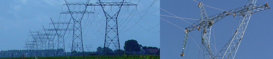
Crossarms used in transmission line basic and tutorials
Cross arms are now almost limited to carrying polyphase circuits in areas where appearance is not of paramount importance. They are also used where lines cross each other or make abrupt turns at large angles to each other.They are used as alley or side arms in which the greater part of their length extends on one side of the pole to provide adequate clearances where pole locations may be affected by limited-space rightsof- way. Cross arms are shown in Figure below.
Uses of cross arms: (a) line arm; (b) side arm; (c) buck arm; (d) double arms.
Loadings
The cross arm acts as a beam, supported at the point of attachment to the pole, and must be capable of being subjected to vertical loadings from the weight of the conductors (encased in ice) and a 225-lb worker (specified as an additional safety measure).
It is also subjected to horizontal loadings stemming from winds and from tension in the conductors where the tensions on each side of the pole do not cancel each other; e.g., where spans or conductors are not the same on each side of the pole, at dead ends, bends, or offsets in the line, or where consideration is given to conductor breaking contingencies.
Stresses
The same principles for determining stresses in beams as were applied in the case of poles may also be applied to cross arms; see Figure below.
Bending Moment
The total bending moment M is equal to the sum of all the individual loads multiplied by their distances from the cross section under consideration. Ordinarily, the weakest section should be at the middle of the arm where it is attached to the pole.
At the pin holes, however, the cross section of the cross arm is reduced and may, under unusual circumstances, be the weakest point in the cross arm. The determination can easily be made by computing unit fiber stress at the several points.
Like the pole, the cross arm acts as a beam and the same formula for determining stresses may be employed:
f = M/ lie
where f = maximum unit fiber stress occurring at extreme edges of cross section, lb/in2
M = total bending moment, in•lb
I = moment of inertia of cross section
e = distance from neutral axis to extreme edge, in
The moment of inertia for a rectangular cross section is
I = 1/12 x bd3 and c = d/2
so that the section modulus
I/c = 1/6 x db3
where the neutral axis is parallel to side d, as shown in Figure below
Product Categories
Contact Us
|
Contact: Ms. Lisa Xiang (Director) Email:lisa.haichung@hotmail.com
Whatsapp:+8613968382831 Add:Xiangshan Ningbo, Zhejiang China.
|
|---|
|
|
|